.svg)
.svg)

.png)
.png)

.svg)
.svg)
Few components are handled, inspected, and documented as frequently throughout their lifecycle as turbine blades. From the initial new part through multiple shop visits until final decommissioning, every blade must be uniquely identifiable: part number, serial number, batch data—increasingly supplemented by machine-readable Data Matrix codes. Laser marking is the established process for this: precise, permanent, and non-contact.
The bottleneck—as is so often the case—is not the laser, but what comes before it: How do you get the blade under the laser with repeatable accuracy? And how do you flip it to the other side when both sides need to be marked? In this article, we show how a robot with the adaptive MATRIX FlexCLAMP gripper solves exactly that: it grips blades of various geometries, holds them in a defined position under the laser, and rotates them to mark the second side—without re-clamping, without part-specific nests, and without setup time.
The challenge: Every blade is different—and many have already been in service
Turbine blades are among the most geometrically demanding mass-produced components in existence. A single large engine contains thousands of individual blades across all compressor and turbine stages, featuring dozens of different geometries—from fan blades to low-pressure turbine blades. These components differ in:
- Length, curvature, and twist of the airfoil
- Root geometry (e.g., fir-tree or dovetail profiles)
- Shrouds, cooling air holes, and sensitive leading and trailing edges
- Material and coating (titanium, nickel-based alloys, thermal barrier coatings)
- Processing state: new part—or overhauled component from maintenance
The last point is often underestimated. In engine maintenance, repair, and overhaul (MRO), an engine is disassembled down to the individual component level. The blades are cleaned and stripped, non-destructively tested, reworked—such as by grinding, blending, or weld overlay—and then recoated. For marking, this has two consequences:
- The original identification is gone. After stripping and reworking, the old marking is often illegible or completely removed. Re-marking is therefore a mandatory step in the overhaul process—before reinstallation, for every single blade.
- The blade no longer matches the nominal geometry. Wear, rework, and new coating thicknesses alter the contour. A rigid fixture designed for a new part only fits to a limited extent.
Added to this is market pressure: industry analyses show the global MRO market reached a record volume of approximately 136 billion US dollars in 2025, and engines account for more than half of the commercial aftermarket in 2026. Shops are operating at capacity limits—every minute of setup time and every additional clamping operation scales with every shop visit.
Requirements: Aviation industry standards for part marking
- Mandatory marking: Aviation authorities require permanent identification of engine components (e.g., 14 CFR Part 45 in the USA). For life-limited parts, the entire history must be traceable back to the point of manufacture.
- Code quality: Data Matrix codes for direct part marking are evaluated according to SAE AS9132. Distortion, contrast, and cell geometry depend directly on the precision of the component's positioning under the laser.
- Low-stress zones: Marking is only permitted in defined, low-stress areas—typically at the root for blades. The marking position is subject to tight tolerances.
- Component protection: Blade surfaces, edges, and coatings must not be damaged during gripping and clamping—dents or pressure marks are not an option on flight-critical components.
In short: The actual marking process takes seconds. The real challenge lies in positioning every blade—whether new or used—accurately and gently. And doing it twice if both sides need to be marked.
The traditional approach: one nest per blade type—plus a second setup for flipping
In many marking cells, the established process looks like this: there is a component-specific fixture for every blade variant into which the part is inserted. If the back needs to be marked, the blade must be removed, flipped, and realigned—or a second, mirrored fixture must be used. With a high variety of parts, this leads to familiar problems:
- Fixture inventory: One nest per variant, often two for double-sided marking—multiplied across the entire blade portfolio.
- Setup times: Every changeover takes minutes. In MRO facilities with a highly mixed parts spectrum, this happens multiple times a day.
- The second setup as a source of error: Every time you reclamp, you have to realign, reset the focus, and accept a new risk of positional errors and compromised code quality.
- Used geometries: Refurbished blades no longer sit properly in new-part nests—leading to shimming, readjusting, and improvising.
- New variants: Every new blade type triggers the design, production, and testing of new fixtures—with lead times of several weeks.
Solution: The robot grips, holds, and turns—MATRIX FlexCLAMP as an adaptive blade fixture
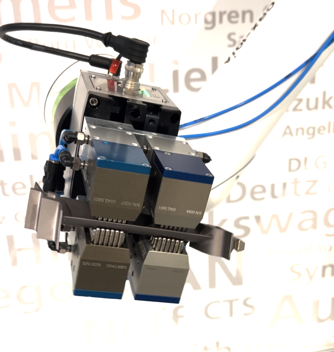
This approach flips the logic: Instead of placing the blade into a matching nest for each side, the gripper itself becomes the fixture. A robot picks up the blade with the MATRIX FlexCLAMP and holds it in a defined position directly within the laser's working field—first with one side, then the other.
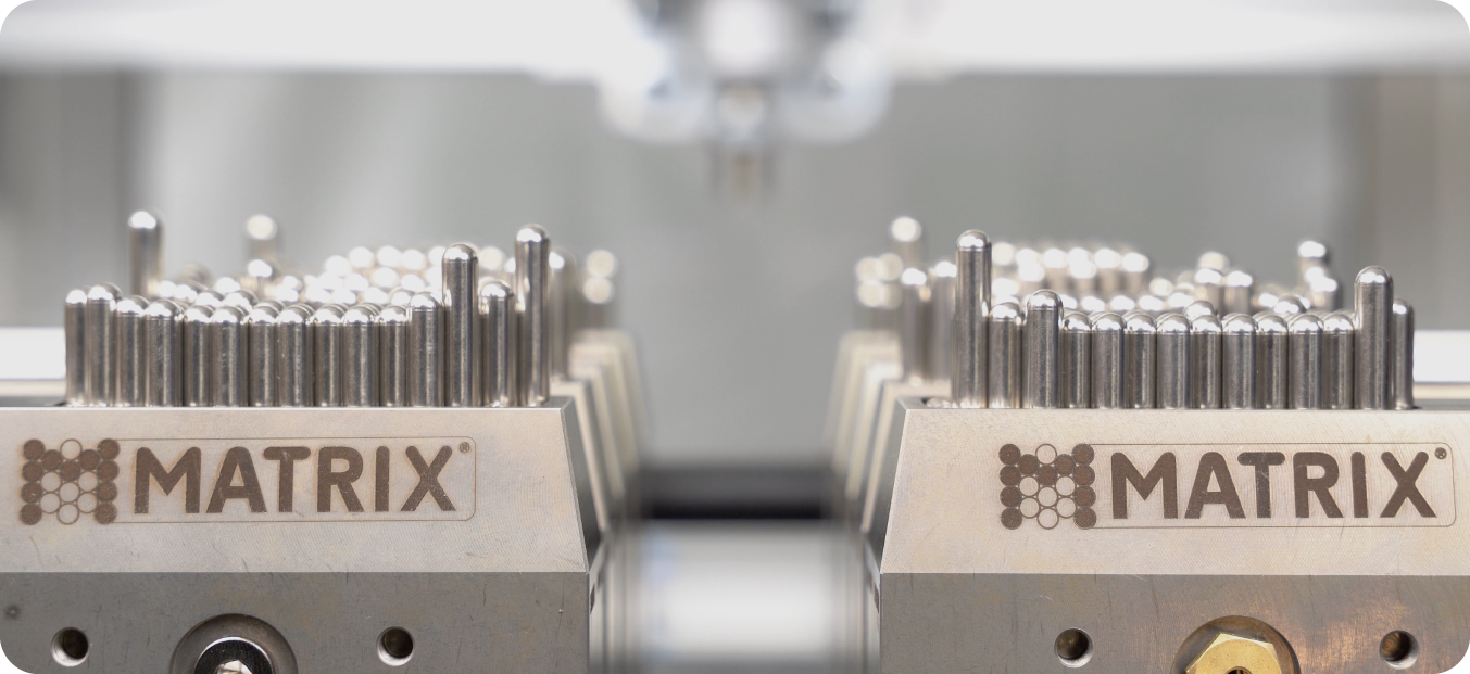
The FlexCLAMP system consists of a multitude of spring-loaded MATRIX pins that conform to the actual contour of the blade when the gripper closes, creating a negative mold of the geometry. The pins are then pneumatically clamped: the shape is locked in, and the gripping force is distributed across the surface. A pressure-free locking mechanism maintains the fixation even in the event of a compressed air failure—a critical safety feature when a robot is moving a flight-critical component over a laser station. Integrated sensors monitor the gripping status and detect deviations before they lead to process interruptions.
The five-step process
- Gripping: The robot removes the blade from the tray or carrier. The pins conform to the actual geometry—regardless of which blade type is being processed—and are locked into place.
- Positioning: The robot holds the blade in a defined, highly repeatable position under the laser. The focus position and marking area are perfectly aligned—no nests, no manual alignment required.
- Marking side 1: Part number, serial number, data matrix code – the laser works while the gripper holds the position steady.
- Rotate instead of reclamping: Because the gripper conforms to the blade, both sides of the root remain fully accessible. For the second side, the robot rotates the blade within the grip to the new marking position – the reference is maintained, with no need for a second fixture or re-alignment.
- Set down and move on: The blade is set down, the clamping is released – and the gripper conforms to the next blade. Even if it is a completely different type: zero setup time.
Why this works specifically with overhauled blades
The decisive difference compared to rigid fixtures: the pins map the actual geometry – not the ideal CAD contour. A blade that deviates from the nominal shape after blending, rework, and recoating is gripped just as securely as a new part. The surface-area force distribution across many pins protects edges, polished surfaces, and coatings – instead of the localized load peaks seen with classic gripper jaws.
In practical terms, this means: new parts and overhauled parts run through the same cell, in the same process, with the same gripper.
Repeatability pays off directly in code quality
The stable, reproducible position has a direct impact on marking quality: constant focus position, undistorted data matrix cells, and marking reliably within the approved zone. This reduces rework and reading errors in all downstream processes – from final inspection to the next shop visit.
Addition: FLEXSTATION and X-SUPPORT for stationary marking fixtures
Not every marking task requires a robot. Where blades are marked or measured in a stationary setup, two additional MATRIX systems complete the picture:
- FLEXSTATION: The CAD-controlled platform creates a contour-adapted, programmable fixture from 3D data (STEP, IGES, DXF) in about 15 minutes – for example, for marking or measuring stations with changing blade types. A US aerospace customer is using this to replace 240 milled fixtures for 120 components with two programmable MATRIX pallets.
- X-SUPPORT: The manual entry-level solution for workstations with a high variety of parts – flexible pin support instead of component-specific nests, with no automation effort required.
We have explained how turbine blades can be clamped for the measurement process using FlexCLAMP and FLEXSTATION in a separate article .
Business Case: The savings potential of an adaptive marking cell
For a blade manufacturer or MRO facility with around 200 active blade variants and double-sided marking, the economic impact can be estimated conservatively. The assumptions: 10–20 variant changes per day, 220 production days, and an existing landscape of component-specific marking nests.
- Elimination of component-specific marking nests (200 variants × approx. €800–€1,500, often double for double-sided marking): approx. €30,000–€60,000 (distributed over several years)
- Reduced setup times (2–4 min. × 10–20 changes/day × 220 days): approx. €15,000–€45,000
- Elimination of the second clamping operation (handling and cycle time savings per blade): approx. €10,000–€20,000
- Less scrap and rework due to incorrect positioning and code distortion: approx. €10,000–€20,000
- Reduced engineering effort for new blade variants: approx. €15,000–€30,000
→ Estimated total savings per cell and year: €60,000–€120,000
Note: These values are based on conservative assumptions for a single marking cell. The effect scales accordingly for multiple cells, larger blade portfolios, or mixed new/overhaul lines. The strategic advantage—introducing new blade types into the cell without the need for fixture lead times—is an additional benefit.
Why now is the right time
- The MRO supercycle is underway. Record volumes in the aftermarket, engines as the largest segment, and shops at capacity limits: throughput per cell is the key lever—and setup time is its greatest enemy.
- Traceability is becoming machine-readable. Direct Part Marking with Data Matrix codes is becoming the standard throughout the entire lifecycle—resulting in more marking requirements and stricter quality standards according to AS9132.
- The skilled labor shortage hits manual work. Manual loading, turning, and alignment tie up the very employees who are needed for inspection and repair.
The bottom line: The gripper becomes the fixture – for new and used blades
The double-sided laser marking of turbine blades is a prime example of where automation in aerospace manufacturing currently hits a snag: not with the laser, not with the robot – but with the challenge of holding thousands of different and sometimes worn geometries with repeatable accuracy. An adaptive FlexCLAMP gripper provides a structural solution: it conforms to every blade, holds it securely during the laser process, turns it without reclamping, and transforms two setups using variant-specific nests into a continuous robotic process with zero setup time.
For engine manufacturers, blade producers, and MRO facilities, this means: new parts and overhauled parts, small and large blades, current and future series – one cell, one gripper, one process.
Your blades, our fixture
If you are marking turbine blades – whether in new production or overhaul – get in touch with us. Based on your CAD data or sample components, we can usually determine within a few days which FlexCLAMP configuration suits your geometries and whether an additional FLEXSTATION fixture would be beneficial.
.svg)


.png "Footer Shadow")